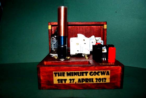
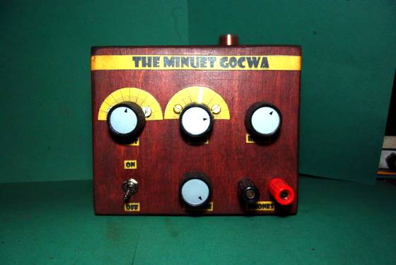
The Minuet
A Single TV Valve Regenerative Radio
By Nick Strong, G0CWA


Hi I am still playing but have gone off the beaten track a bit with my choice of valves for this my latest set, The Minuet (Minute). This set is small for me being only around a five inch square base.
I decided as an aside from my usual sets using “Recognised Valves” for radio I would try some of my old stock of TV valves, This set is based on a PCF80, a TV audio Triode Pentode (a PCF 802 works just as well and is pin compatible, I’ve tried it).
The Circuit
No originality is claimed for the circuit configuration, just the valve type used. I have never seen this “Family” of valves used in home radio construction.
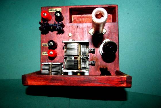
The circuit consist of a standard pentode regen detector/af amplifier with a tapped Tuning or Tank coil plugging in to a standard 7 pin din socket. The use of a socket for plug in coils is not unusual. But the use of a Din plug and socket is, it is allot easier and cheaper to get these than the more generally accepted octal ones.
The Tank circuit is tuned by a dual gang variable capacitor which by a link on the din plug can have its gangs used singly or in parallel so varying the tuning range of the set.
The reduced range is very useful on the shortwave bands.
The actual tuning range of the radio will vary depending on both the value of capacitor and inductance used. The tap for the cathode, regeneration feedback, is a select on test setting for best performance but around 20% up from ground is a good starting point.
The tuning range and inductance can be calculated by either my mystery coil calculator on makearadio.com or the Professor Coyle calculators.
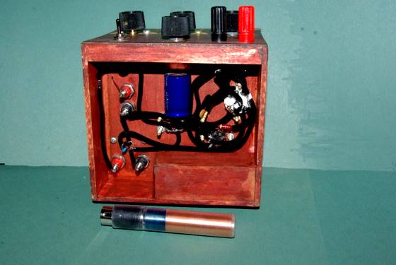
The detector is then followed by a simple triode af amplifier stage feeding a pair of high impedance head phones.
The set works well from 12V to around 30V Supply, obviously being more sensitive the higher the supply voltage. The only disadvantage being the valve heaters require 9V rather than the more usual “standard voltages”. The valve heater supply is controlled by both a series dropper resistor and an LM7809 so the power dissipation of the regulator does not exceed its maximum ratings. If R2 is around 10 ohms the set will work between 12 and 15V supply. A “standard radio supply” is 13.8V a perfect supply voltage.
In conclusion it is worth looking at untried valves for building any set, there is a large number of ex TV valves that will be suitable and give very good results at low HT. I have only tried this radio on MW but don’t see any reason why it shouldn’t work on LW or the SW bands with suitable coils.
Hope you found this set interesting food for thought and would love to hear your comments if you play with this basic design.
As usual I can be contacted at [email protected] or via the Radio Board
Enjoy Building 73 de Nick G0CWA